¶ Calibrate Magneto X OrcaSlicer for Specific filament
This document provides a guide on how to quickly find the best printing parameters for a new material after switching. The right printing parameters greatly enhance print quality.
¶ 1. Main Steps for Material Adaptation
To adapt a new material, we identify the following optimal parameters in sequence:
- Optimal Printing Temperature
- Maximum Extrusion Flow
- Optimal Flow Ratio
- Best Pressure Advance Value
These steps are conducted assuming the nozzle diameter, melt pool length, and printing speed are already determined. If there are changes to these three factors, the parameters may need fine-tuning.
¶ 2. Execution of Each Step
¶ 2.1 Optimal Printing Temperature
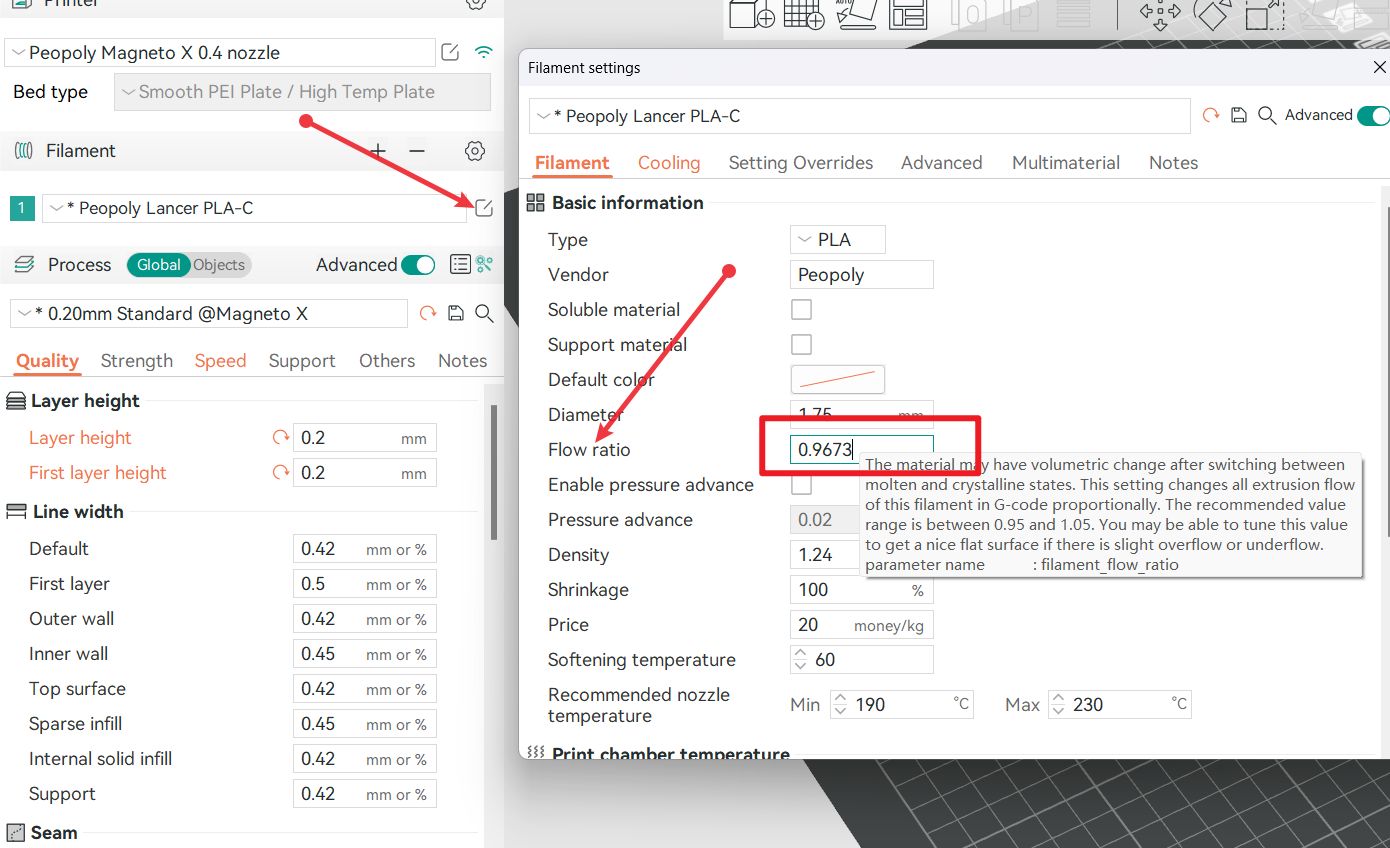
First, open your slicing software. Let's take PLA as an example to complete a material printing temperature adaptation.
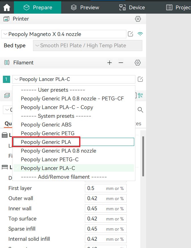
After selecting general PLA as shown above, adjust your desired printing speed.
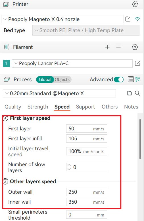
Change the print speed.
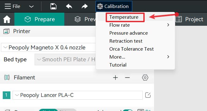
Then, choose the calibration temperature.

Slice this model and print it out.
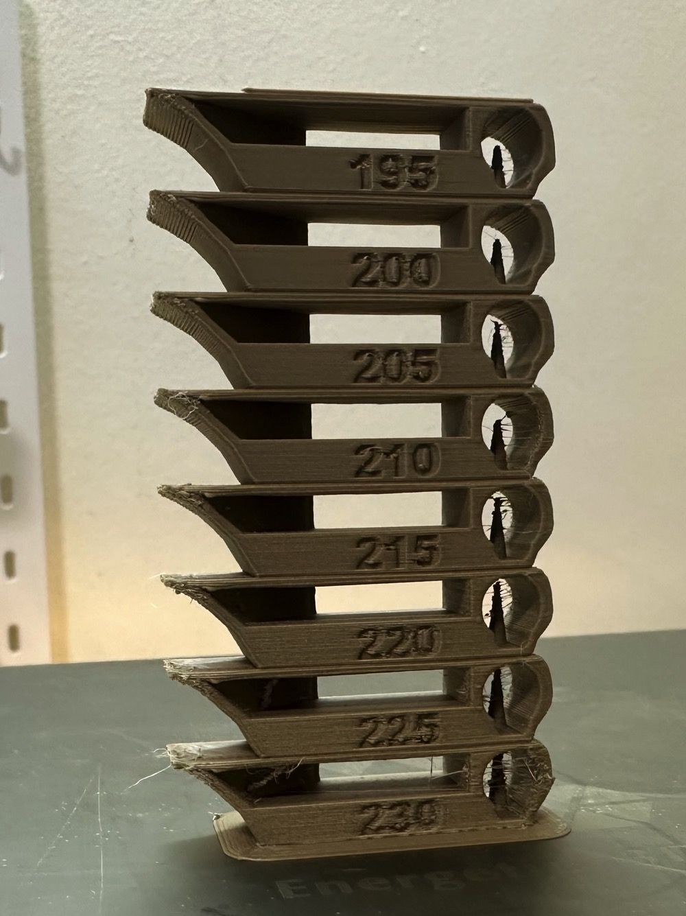
Choose the temperature that yields the best printing effect as your printing temperature.

For instance, in the above image, we would select 200 degrees as the optimal printing temperature.
¶ 2.2 Maximum Flow Test
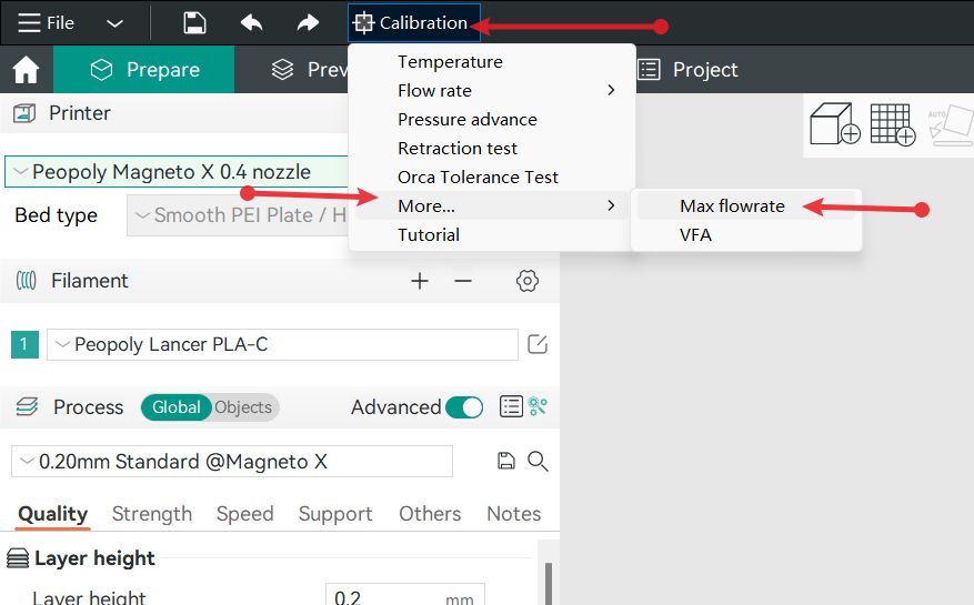
The maximum flow of a material greatly depends on the extruder, the type of material, and the heating temperature. Once the printing temperature is confirmed, test the maximum flow that this material can achieve at that specific printing temperature. The maximum flow directly affects the highest printing speed that can be supported.
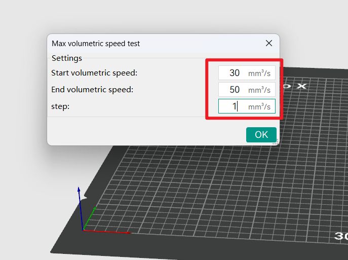
In the dialogue box shown below, enter the initial and final flow values:
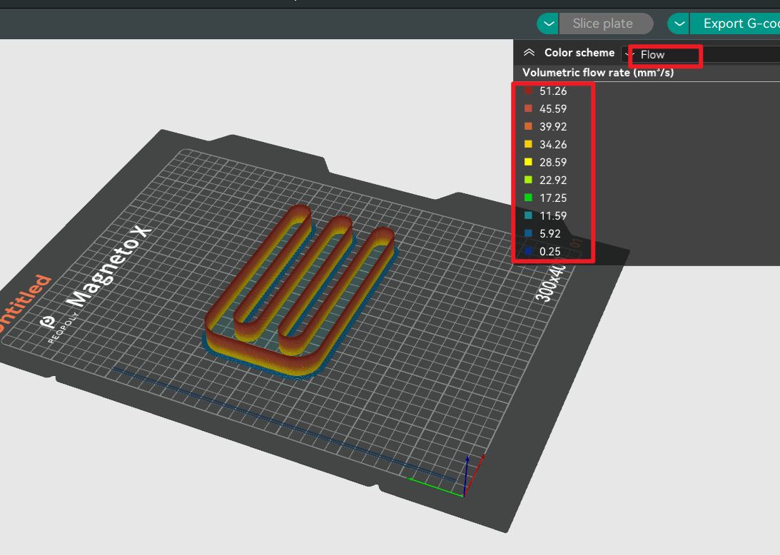
After slicing, you can see the G-code's flow changes in the slice preview:
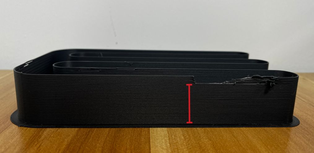
Print the model as shown below.
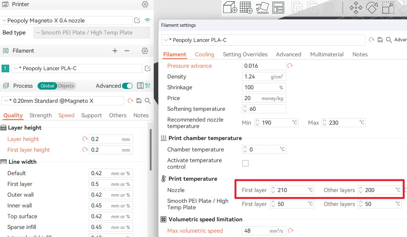
Measure the height from the very bottom to the first instance of unstable extrusion, as indicated by the red mark in the image. For example, if our initial maximum value is set at 30mm3/s, and the height marked in red is 18mm, then the calculated maximum flow value is: 30 + 18 = 48mm3/s
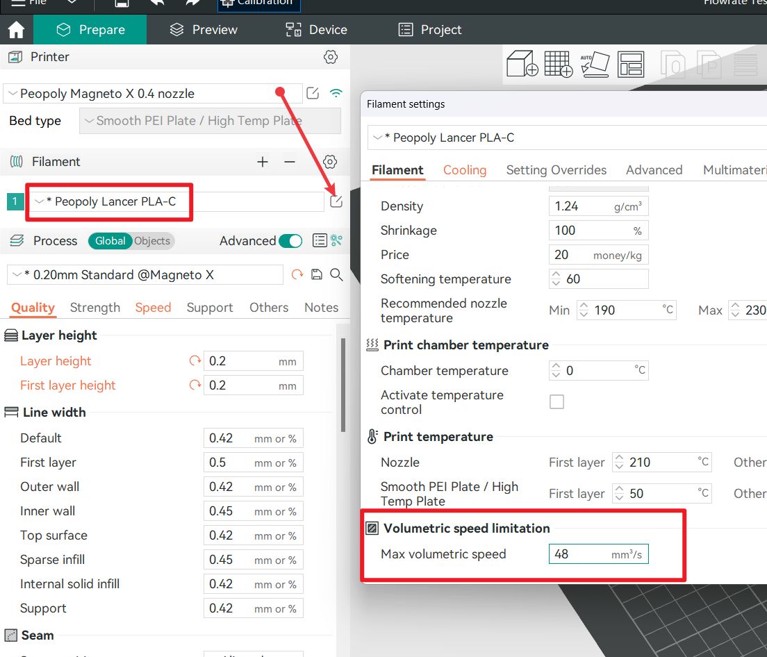
Fill in the result 48mm3/s obtained above to the position shown in the figure below :

¶ 2.3 Optimal Extrusion Ratio
Each material type varies in extrusion smoothness. Adjusting the extrusion ratio helps achieve more accurate print line width.
Calibrating the flow rate involves a two-step process.
Steps:
¶ Step 1
Select the printer, filament, and process for the test.
¶ Step 2
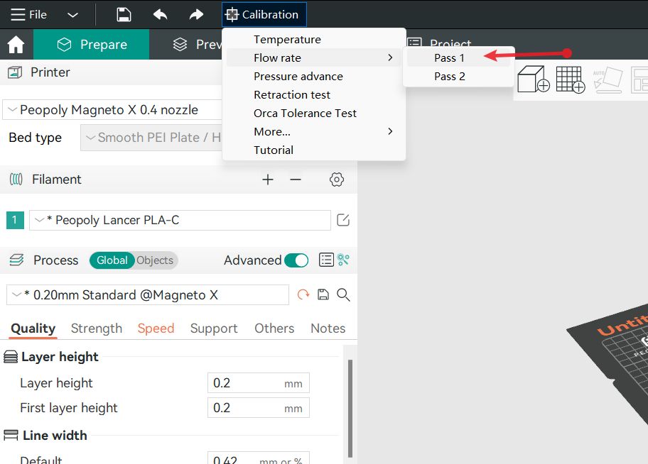
Select Pass 1 in the Calibration menu
The following model will be generated after the above selection:
¶ Step 3
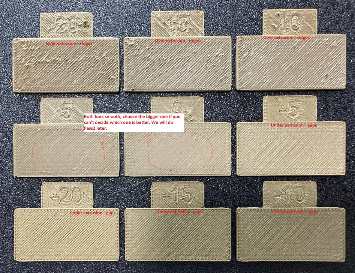
Examine the blocks and determine which one has the smoothest top surface.
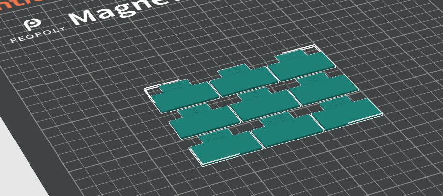
Print the blocks:
¶ Step 4
Update the flow ratio in the filament settings using this formula: FlowRatio_old*(100 + modifier)/100. If your previous flow ratio was 0.98 and you selected a block with a +5 flow rate modifier, the new value should be: 0.98*(100+5)/100 = 1.029. Remember to save the filament profile.
¶ Step 5
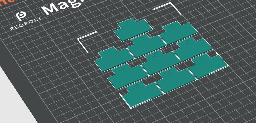
Perform the Pass 2 calibration, similar to Pass 1 but with a new project of ten blocks, ranging from -9 to 0 in flow rate modifiers.

Repeat Steps 4 and 5. For example, if your previous flow ratio was 1.029 and you selected a block with a -6 flow rate modifier, the new value would be: 1.029*(100-6)/100 = 0.96726. Remember to save the filament profile.
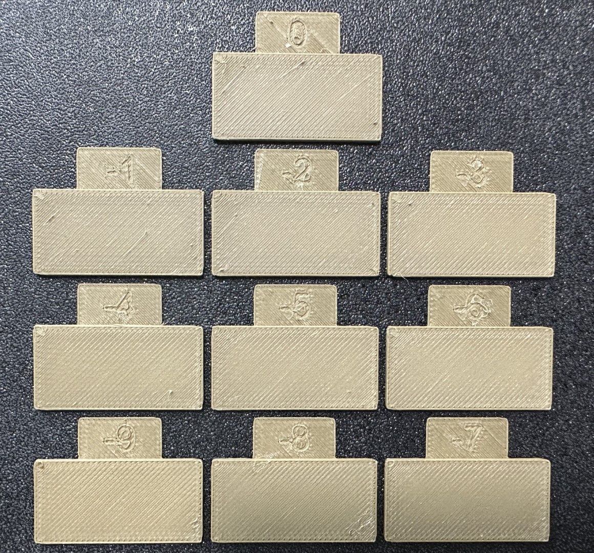
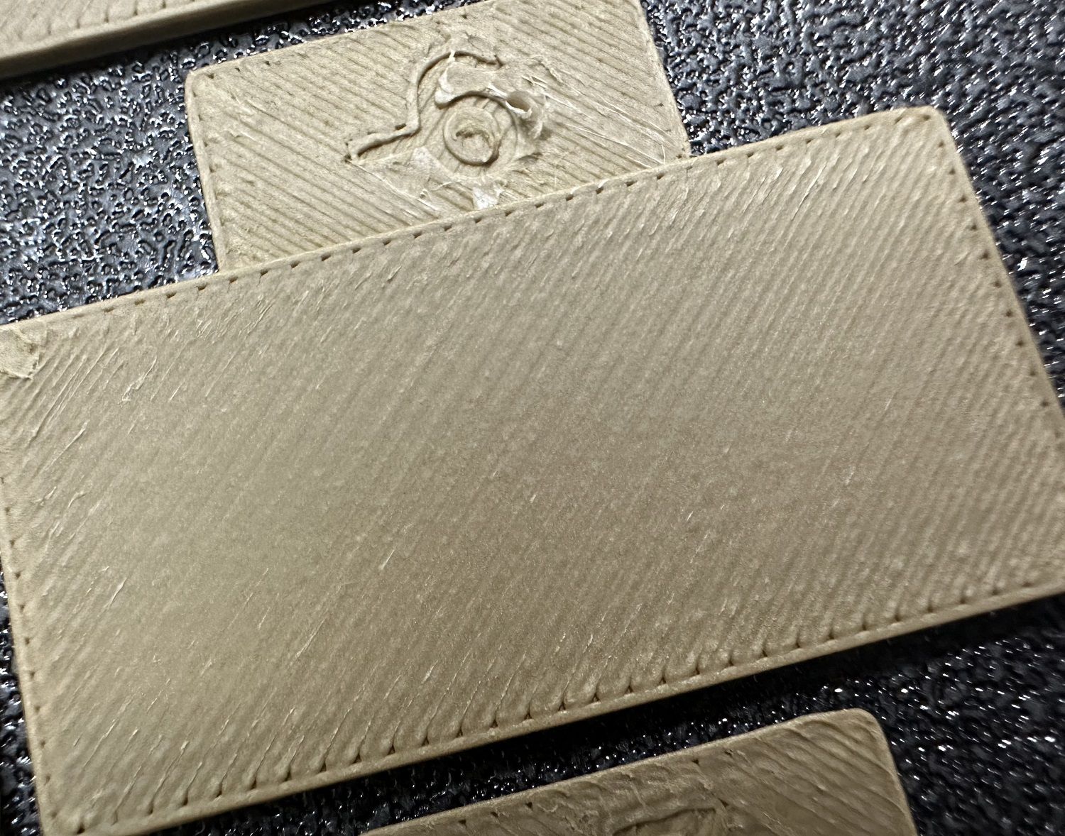
The best result:
¶ 2.4 Pressure Advance Value
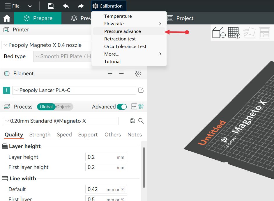
Magneto X defaults to using the tower method to test the pressure advance value.
Follow the below image to find the PA value adjustment button.
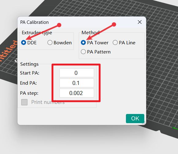
Generate the following model, slice it, and then upload it to the printer for printing.
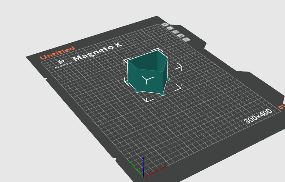
The tower method may take more time but does not rely on the quality of the first layer. The PA value for this test will increase by 0.002 for every 1 mm increase in height.
Steps:
Select the printer, filament, and process for the test.
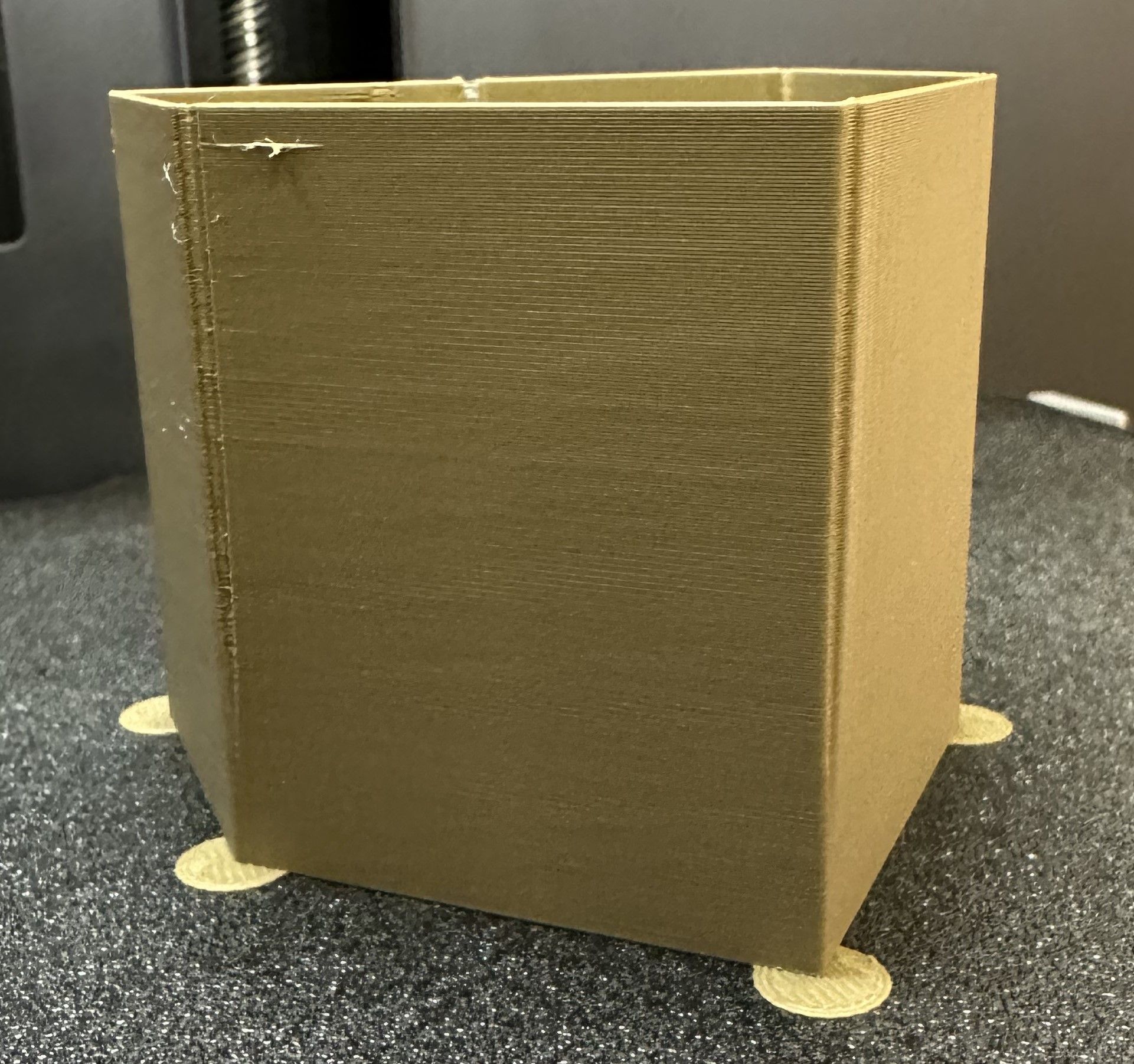
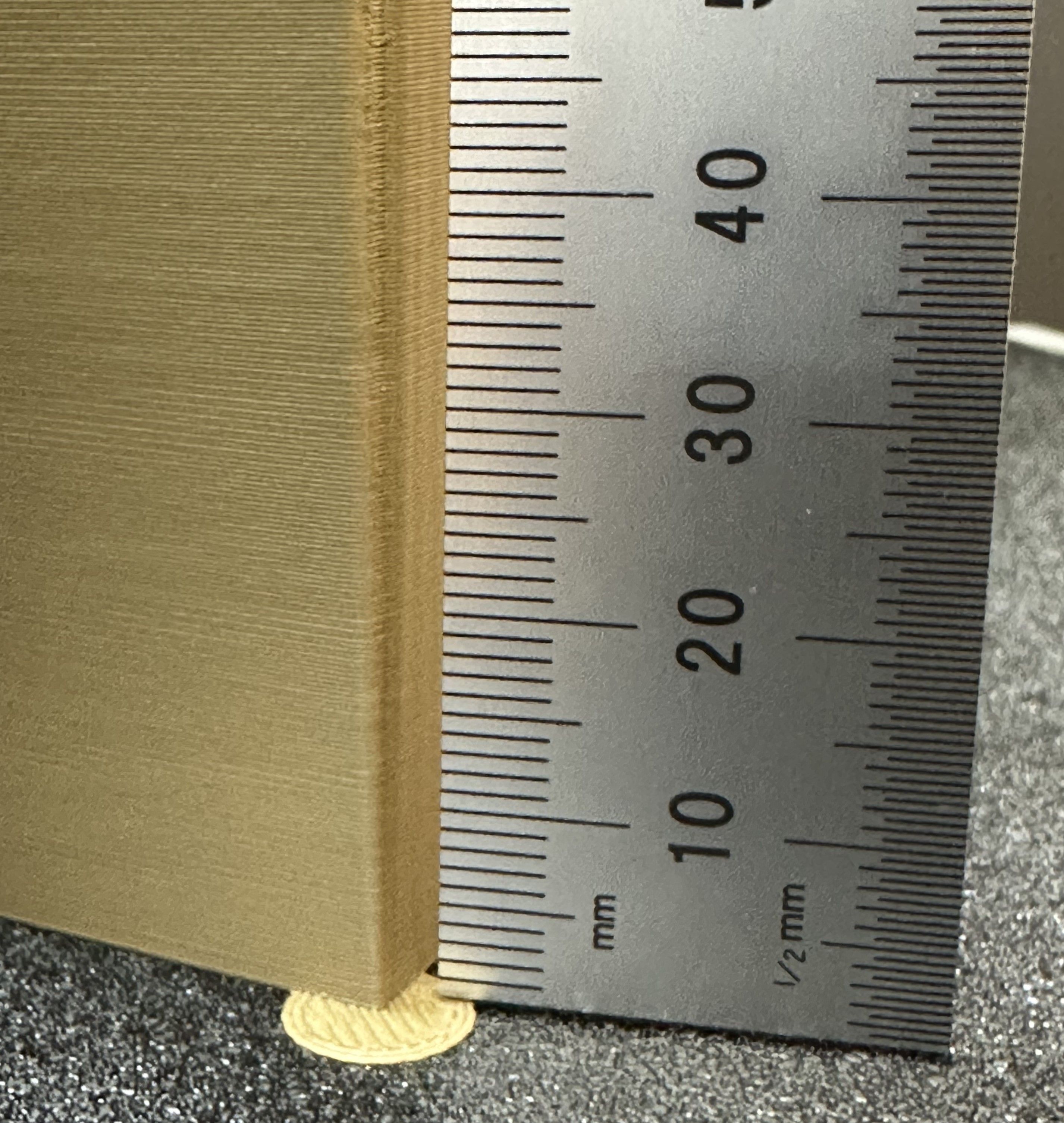
Examine each corner of the print and mark the height that yields the best overall result.
In this case, a height of 8 mm was selected, so the pressure advance value should be calculated as 0.002*8 = 0.016.
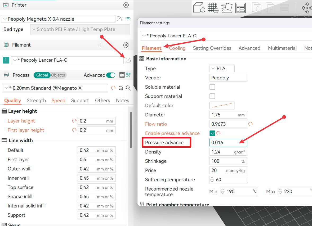
Enter the calculated value in the position shown in the image below:
Reference document: https://github.com/SoftFever/OrcaSlicer/wiki/Calibration