¶ Lancer Toolhead PCB
This document primarily introduces the toolhead motherboard in the Lancer Extrusion System.
The toolhead motherboard is the most critical electronic component in the Lancer extrusion system. It communicates with the Klipper motherboard via CANBus, and all other connections are integrated onto the RP2040 chip for processing.
The toolhead consists of two MCUs: one is the RP2040, and the other is the 8051. The 8051 is mainly responsible for collecting and analyzing data from the load cell sensor and outputting high and low-level signals. The RP2040 implements the CAN protocol and configures all Klipper-related control pins.
This document will provide detailed information about the hardware interfaces and the corresponding software configuration settings.
Specifications:
- Main control chip: RP2040
- Communication interfaces: USB / CanBus
- Power supply: 24V
- Output interfaces:
- 1 x Hotend Fan
- 2 x Parted Fan
- 2 x Heater
- 1 x Thermistor
- 1 x Type C
- 1 x CanBus
- 1 x Stepper Motor
- 1 x Load Cell Data Port
¶ 1. Interface Introduction
¶ Interface Introduction

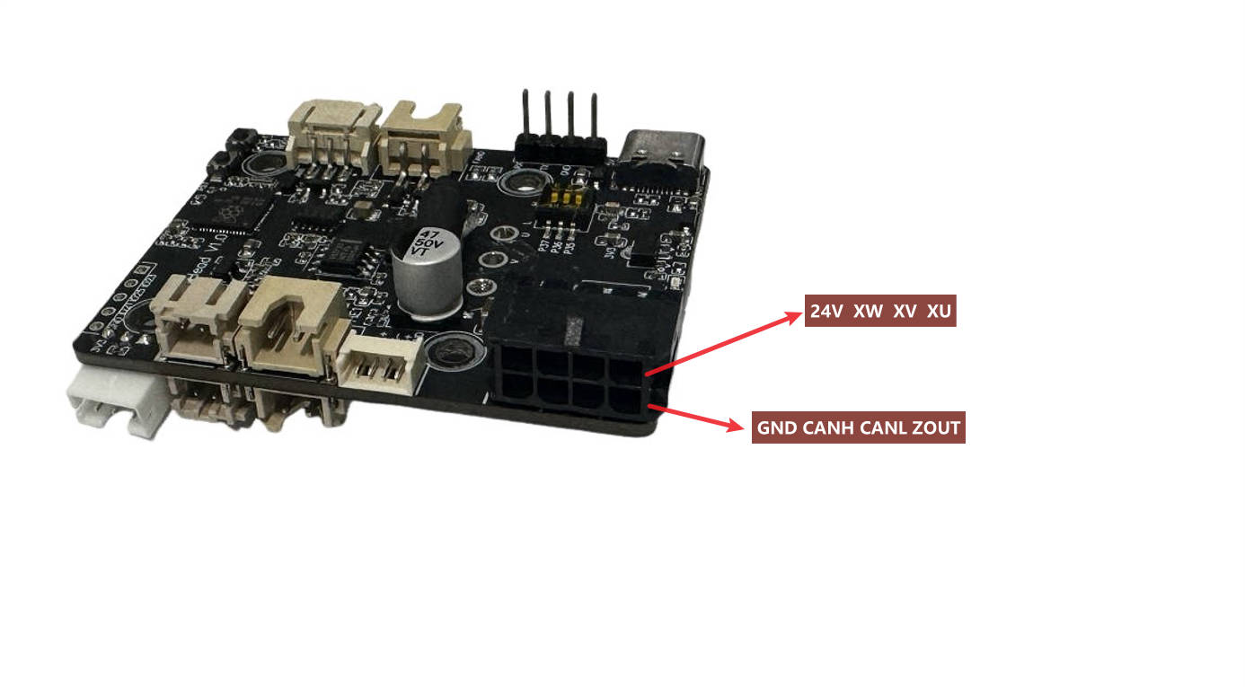
PCB Backside Interfaces:


Regarding the mainboard interfaces mentioned above, the following clarifications are provided:
- There are two heater pins, but they are controlled by the same pin (GPIO). When connecting to a long melt pool, two interfaces will be used.
- The protect pin is a reserved temperature sensor interface connected to another MCU, which can be used to monitor the nozzle temperature.
- There are two part fans, controlled by two different pins.
- Probe LED: When the load cell value exceeds the threshold, a red light will be lit; otherwise, it will continuously show green.
- Among the Canbus & 24V interfaces, there is also a load cell trigger output pin.
- ZOUT pin is the loadcell probe pin, it is connect to BTT MCU pin(PE12) in the bottom
¶ Interface Pin Descriptions
The following table provides the RP2040 pin numbers for each interface.
| Interface Description | Pin Number |
|---|---|
| Step motor dir | GPIO4 |
| Step motor plus | GPIO5 |
| Step motor enable | GPIO10 |
| Step motor uart | GPIO6 |
| Heater pin | GPIO0 |
| Temperature sensor pin | GPIO26 |
| Part Fan 0 | GPIO2 |
| Part Fan 1 | GPIO11 |
| Hotend Fan | GPIO1 |
| Filament runout sensor | GPIO29 |
| Loadcell overload pin | GPIO25 |
| Loadcell reset pin | GPIO24 |
| Filament Load Button | GPIO20 |
| Filament Unload Button | GPIO27 |
| Input Shaper ADXL34 CS pin | GPIO13 |
| Input Shaper ADXL34 SCLK pin | GPIO14 |
| Input Shaper ADXL34 MOSI pin | GPIO15 |
| Input Shaper ADXL34 MISO pin | GPIO12 |
¶ 2 Configuration Reference
For detailed configuration references, please visit Peopoly's GitHub:
https://github.com/mypeopoly/magneto-x-klipper-config/blob/main/config/magneto_toolhead.cfg
¶ 3 Installation Reference
Below is the hole position diagram of the LancerToolhead motherboard:
